Valve symbols are an essential visual language used in Piping and Instrumentation Diagram (P&ID). They help engineers, technicians, and maintenance teams quickly understand how fluid flows through a system. This article introduces the most common valve symbols and explains how to read them effectively.
What is a Valve Symbol?
When you look at industrial plumbing, HVAC, or fluid-system diagrams — like Piping & Instrumentation Diagram (P&ID) drawings — you won’t see actual pipes, valves, or fluid lines. Instead, engineers use valve symbols: simplified graphical icons that stand in for physical valves. These symbols represent different types of valves (e.g. gate, ball, butterfly) and sometimes the method of actuation (manual, electric, pneumatic, etc.).
Using standard symbols keeps diagrams compact, consistent, and readable — and helps engineers, builders, maintenance crews, and inspectors understand fluid flow, control points, and where valves are located.
Why Valve Symbols Matter
- Clarity & Communication: Standard symbols allow different engineers to understand diagrams consistently.
- Safety & Maintenance: Symbols convey valve type, actuation method, and purpose — important for safe operation.
- Design & Documentation: Accurate valve symbols guide contractors on placement, type, and functionality.
Common Valve Symbols
Here are some of the most common valve types and how they are typically symbolized in P&ID diagrams.
| Valve Type | Symbol Description | Typical Use |
|---|---|---|
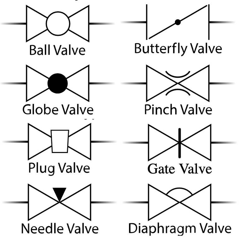
| Gate Valve | A straight line through pipe with a perpendicular bar (or wedge-shaped interrupt) across it. | Used to start or stop flow — provides an unobstructed passage when open, full shutoff when closed. |
| Globe Valve | Often shown using a "bow-tie" or hourglass-like symbol (sometimes similar to gate valve symbol — exact type may be clarified in legend). | Used for regulating or throttling flow — ideal when you need fine control, not just on/off. |
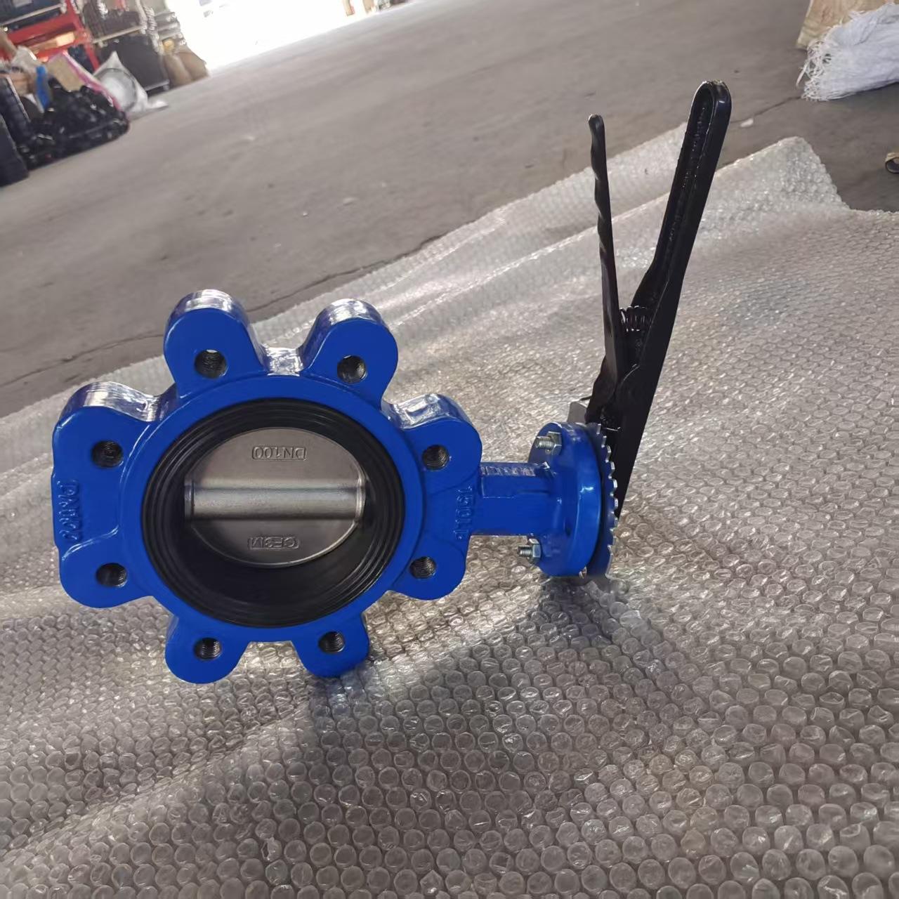
| Ball Valve | A circle (representing the ball) inside the valve body, often with a "T-bar" or lever symbol to indicate orientation (open/closed). | Used for quick shut-off — widely used because they are robust and easy to operate. |
| Butterfly Valve | A circle (valve body) with a line (representing the disc) inside, often through the center. | Used for moderate flow control or shut-off, especially useful in large-diameter pipes or where space/weight is limited. |
| Check Valve (One-way Valve) | Typically represented by a line with an arrow or a "T-shaped" symbol at one end to show flow direction. | Allows fluid to flow in only one direction — prevents backflow and protects pumps / system integrity. |
| Control / Actuated Valves | Valve body plus extra symbols: triangles pointing toward each other (for the valve body) plus actuator icons (springs, motors, pneumatic dome, etc.) to show how the valve is operated. | Used when you need remote control, automated operation, or precise control (e.g. in process plants, HVAC, chemical lines). |
How to Read Valve Symbols
Here is a step-by-step guide on how to read valve symbols.
- Look at the valve body shape first. That gives you a first hint of valve type (gate, ball, butterfly, etc.).
-
Check for flow-direction markers. Some valves — especially one-way or check valves — include arrows or directional symbols.
Tameson.com - See if there’s an actuator symbol. If you see extra drawing elements (spring, motor symbol, pneumatic dome), that means the valve is actuated remotely or automatically.
- Refer to the legend. Because different industries or companies might use slightly different conventions, always check the diagram’s legend or notes for exact meaning.
- Understand the function: shut-off, throttling, one-way flow, safety. A proper valve symbol — once correctly interpreted — tells you not just what the valve is, but what it does in the system.
Best Practices When Using or Interpreting Valve Symbols
- Always ensure the drawing follows a recognized standard. Many diagrams rely on universal standards like ISO 14617 (esp. Part 8 for valves & dampers) to maintain consistency.
- When designing or modifying systems, keep valve symbols simple but unambiguous: clarity beats cleverness — especially in complex piping networks.
- If you’re working across teams (designers, operators, maintenance), ensure everyone agrees on symbol usage and ensures the legend is present on diagrams.
- Use correct actuator & flow-direction annotations. Without these, a valve symbol can be misleading — e.g. a check valve without arrow might be confused with a simple closed-shut valve.
- For safety-critical systems (e.g. pressure relief, chemical lines), double-check that valve types and functions are correctly documented and confirmed in the legend.
Quick Reference When to Expect What Valve Symbol
| Scenario / Requirement | Use Valve Symbol For |
|---|---|
| Need to shut off flow completely (on/off) | Gate valve or Ball valve |
| Need quick shut-off but compact size | Ball valve |
| Need to throttle or regulate flow | Globe valve or Butterfly valve |
| Need to prevent backflow / ensure one-way flow | Check valve |
| Need remote or automated control (actuation) | Control valve with actuator symbol |
| Large diameter pipe with space constraints | Butterfly valve (lightweight, compact) |
3 Way Valve Symbol
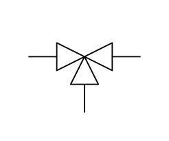
A 3-way valve symbol typically shows three ports arranged in a "T" or "L" configuration. In P&ID diagrams, the symbol often includes a movable internal element or switching arrow that indicates which ports are connected during operation.
These valves are used to mix two fluid streams, divert one stream into two different directions, or alternate flow paths. Always check the legend to confirm whether the symbol represents a mixing or diverting configuration.
What Does the Relief Valve Symbol Mean?
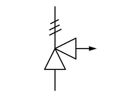
A relief valve symbol usually shows a spring-loaded mechanism, often drawn with a diagonal spring over the valve element. The symbol indicates that the valve opens automatically when system pressure exceeds a preset limit.
Relief valves protect piping, pumps, and vessels from overpressure conditions. The symbol may also include set pressure values or actuator details depending on the diagram standard used.
What Are Common Hydraulic Valve Symbols?
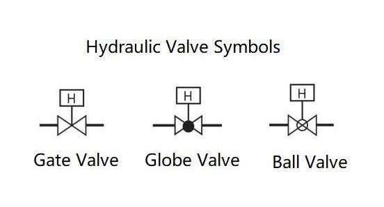
Hydraulic valve symbols follow ISO 1219-1 conventions and typically use stacked squares to show the number of flow positions. Arrows within the squares indicate flow paths, while blocked sections show closed positions.
Common hydraulic symbols include:
- Directional control valves (DCVs)
- Pressure relief valves
- Check valves
- Flow control valves
- Proportional and servo valves
Each symbol provides information about valve type, actuation method, port count, and operating logic.
How to Read Directional Control Valve Symbol
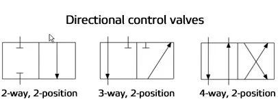
Directional control valve (DCV) symbols use multiple squares to represent different operating positions. Each square shows the internal flow path for that position. The number of squares equals the number of valve positions, and the number of ports is shown around the block.
Actuation icons (solenoids, springs, manual levers) are placed on each side to indicate how the valve shifts between positions. Reading these symbols involves tracking how flow paths change when the valve is actuated.
How to Read Pneumatic Valve Symbols
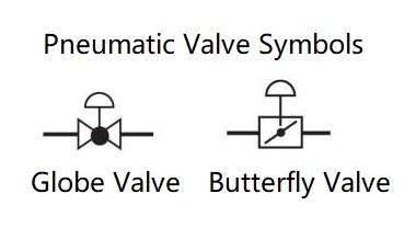
Pneumatic valve symbols follow the same block-diagram style used in hydraulics, but with air-specific annotations. Arrows indicate air flow, while T-shaped blocks represent closed ports.
Actuation methods — such as pilot signals, solenoids, push-buttons, or rollers — are shown with unique icons. Exhaust ports may also be marked with a small triangle or vent symbol. Understanding pneumatic symbols helps identify how compressed air is distributed and controlled through a system.
What Do the Symbols on Radiator Valves Mean?
Radiator valves often include simple symbols indicating temperature or flow settings. Common icons include snowflake (frost protection), numbers or dots (temperature levels), and fully open/closed indicators.
In diagrams, radiator valve symbols are usually shown as simplified throttling or thermostatic valve icons. These symbols help identify whether the valve provides manual flow control or automatic temperature regulation.
What Is the Symbol for a Check Valve?
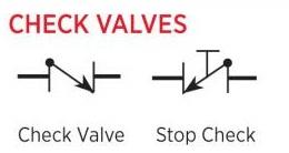
A check valve symbol typically includes a small ball or flapper drawn against a seat, with an arrow pointing in the allowed flow direction. When flow attempts to reverse, the internal element closes, preventing backflow.
In P&ID standards, the symbol may vary slightly, but it always communicates one-way operation. Double-check valves or spring-loaded check valves include added notations such as springs or secondary arrows.
Conclusion
Valve symbols — though very simple in appearance — provide critical information about flow control, safety, and system design. Once you understand the basic symbols and how to interpret actuators and direction indicators, even complex P&ID diagrams become easy to read.